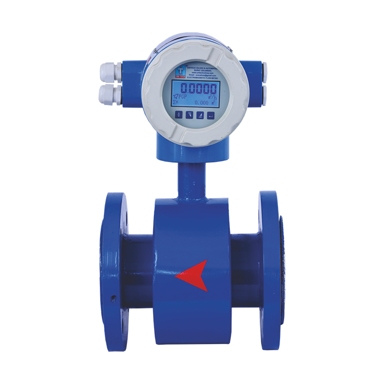
Electromagnetic Flow Meter
Reference Standard
Uni-Tech's Electromagnetic flow meter model U-MAG 20 is designed for flow measurement of conductive liquids with no moving parts and a PTFE lining. Electromagneticflow meter is suitable for measurement of flow of conductive liquids, which is based on Faraday's law of Electromagnetic induction, according to which a voltage is induced in electrically conducting body moving in a magnetic field & this voltage is directly proportional to the velocity. Standard outputs include analog, frequency, Rs485 or GSM/GPRS connectivity. Local-and remote-display models are available. They meet the most demanding requirements on high measurement precision, long-term stability and hygienic standard.
Design Features
| Display Version | Integral Mounted(Default), Remote Display |
|---|---|
| Display | LCD Graphical Display |
| High Accuracy | Up to 0.5% accuracy (Standard 1% Accuracy) |
| Wide Flow Range | Diameter from 15mm to 500mm |
| Resolution | 5 digits Flowrate, Totalizer, 10 digits Totalizer |
| Electrode Meterial | SS 316L (Default) Hastelloy C/Titanium/Tantalum |
| Application | All Conductive liquids having conductivity >20u/cm |
| Empty Pipe Detection | Yes |
Output
| Retransmission | 4-20mA (Opto & Galvanic Isolated) |
|---|---|
| Control Alarm | Max 2 Relay on Flow Rate |
| Batch Control Relay | Control Relay on Totalizer for Batching Function |
| Pulse Output | Pulse Corresponds To Totalizer Quantity |
| Communications | RS 485 Compatible |
| GPS / GPRS Modem (Telemetry) | Available (On Request) |
Electronics Parameters
Configuration Functions / Parameters
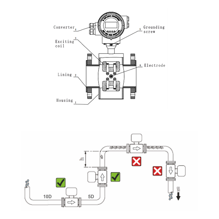
Sensor Description (Mechanical Parts)
| MM | Inch | Face To Face Distance | Height | Flange Diameter | Pitch Circle Diameter (PCD) | Dia. of Hole | Thickness | Number of Holes |
|---|---|---|---|---|---|---|---|---|
| - | - | A | D | E | F | H | I | - |
| 15 | ½" | 200 | 117 | 88.9 | 60.4 | 15.7 | 11.2 | 4 |
| 20 | ¾" | 200 | 126 | 98.6 | 69.9 | 15.7 | 12.7 | 4 |
| 25 | 1" | 200 | 136 | 108 | 79.2 | 15.7 | 14.2 | 4 |
| 32 | 1¼" | 200 | 145 | 117.3 | 88.9 | 15.7 | 15.7 | 4 |
| 40 | 1½" | 200 | 155 | 127 | 98.6 | 15.7 | 17.5 | 4 |
| 50 | 2" | 200 | 180 | 152.4 | 120.7 | 19.1 | 19.1 | 4 |
| 55 | 2¼" | 200 | 206 | 177.8 | 139.7 | 19.1 | 22.4 | 4 |
| 80 | 3" | 200 | 218 | 190.5 | 152.4 | 19.1 | 23.9 | 4 |
| 100 | 4" | 250 | 258 | 228.6 | 190.5 | 19.1 | 23.9 | 8 |
| 125 | 5" | 250 | 282 | 254 | 215.9 | 22.4 | 23.9 | 8 |
| 150 | 6" | 300 | 307 | 279.4 | 241.3 | 22.4 | 25.4 | 8 |
| 200 | 8" | 350 | 372 | 342.9 | 398.5 | 22.4 | 28.4 | 8 |
| 250 | 10" | 400 | 434 | 406.4 | 362 | 25.4 | 30.2 | 12 |
| 300 | 12" | 450 | 511 | 482.6 | 431.8 | 25.4 | 31.8 | 12 |
| 350 | 14" | 550 | 570 | 533.4 | 476.3 | 28.4 | 351.1 | 12 |
| 400 | 16" | 610 | 630 | 596.9 | 539.8 | 28.4 | 36.6 | 16 |
| 450 | 18" | 660 | 670 | 635 | 577.9 | 31.8 | 39.6 | 16 |
| 500 | 20" | 750 | 740 | 698.5 | 635 | 31.8 | 42.9 | 20 |
Flow Rate Characteristics Valve
| Line Size | Flow Range (㎥/hr) For Velocity 0.3m/s to 6m/s | ||
|---|---|---|---|
| Inch | NB | Min | Max |
| ½" | 15 | 0.19 | 3.817 |
| ¾" | 20 | 0.33 | 6.785 |
| 1" | 25 | 0.53 | 10.602 |
| 1¼" | 32 | 0.86 | 17.371 |
| 1½ | 40 | 1.35 | 27.143 |
| 2" | 50 | 2.12 | 42.1415 |
| 2½" | 65 | 3.58 | 71.675 |
| 3" | 80 | 5.42 | 108.573 |
| 4" | 100 | 8.48 | 169.646 |
| 5" | 125 | 13.25 | 265.071 |
| 6" | 150 | 19.085 | 381.703 |
| 8" | 200 | 33.929 | 678.584 |
| 10" | 250 | 53.014 | 1060.28 |
| 12" | 300 | 76.340 | 1526.81 |
| 14" | 350 | 103.908 | 2078.16 |
| 16" | 400 | 135.716 | 2714.33 |
| 18" | 450 | 171.766 | 3435.15 |
| 20" | 500 | 212.057 | 4241.15 |
Applications
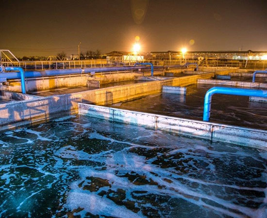
Water & Waste Management
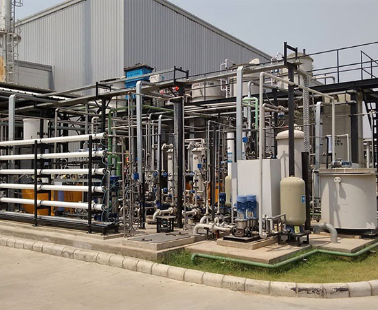
ETP Plant

Pharmaceuticals Industries

Power Industries

Cement Industries
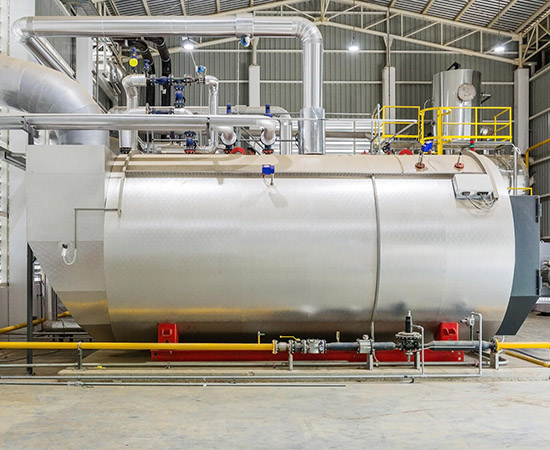
Water Heating Industries
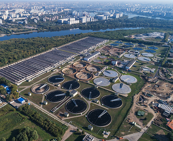
Sewage Treatment Plant

Mining Industries
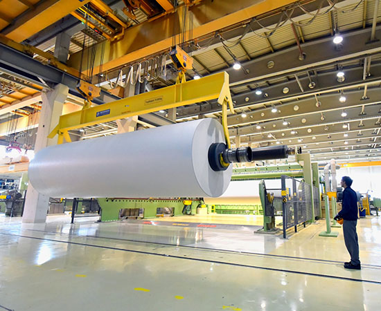
Paper & Pulp Industries

Food / Beverage Industries